Click on image to enlarge.
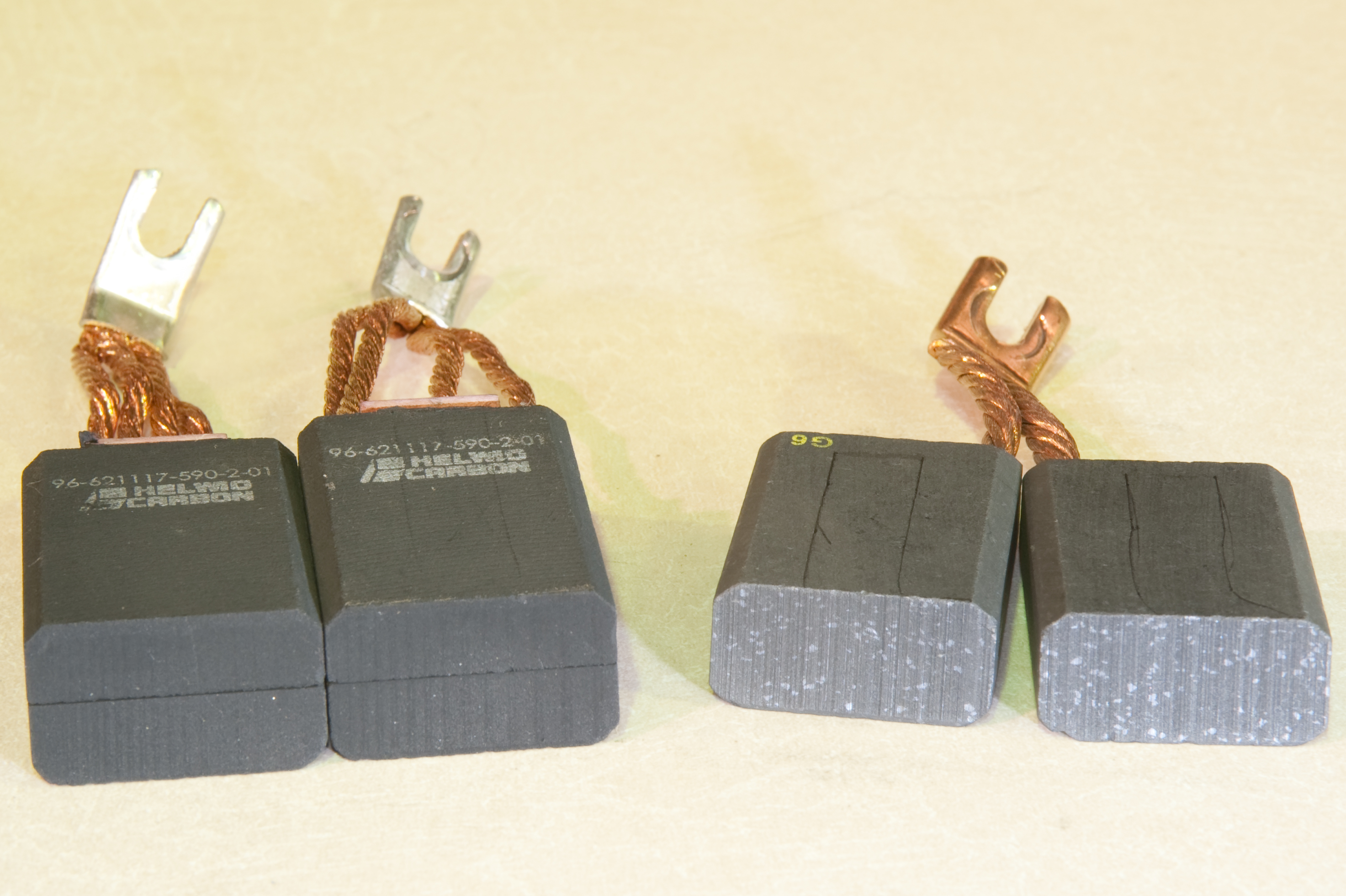
Size Matters!
Compare our WarP 9 brush size to those used by competitors!
You want the best commutation you can get for your motor!
Our extra large brushes are designed for high voltages and currents.
Our motors use specially formulated brushes manufactured exclusively for our motors.
Bigger IS better!
Four wires going to each brush (2 per wafer), versus the more common two wires.
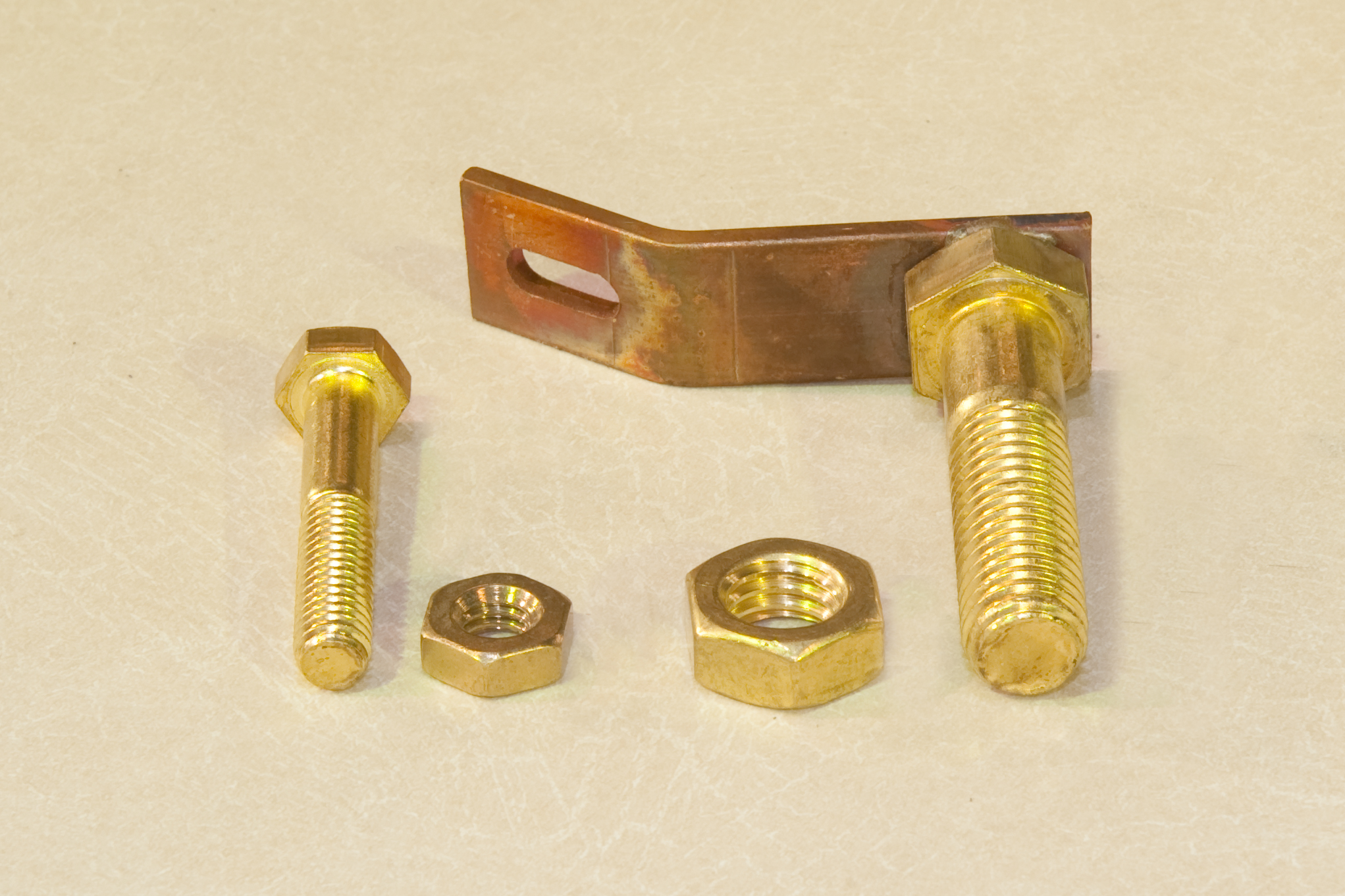
Heavy Duty!
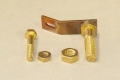
Most manufacturers use 3/8" (or smaller) terminal studs.
Our WarP 9 Motors use 1/2" terminal studs! Which would you prefer?
|
The Next generation of WarP
™ Motors !
(More changes coming soon - 1.12" CE shafts - 7/26/2011)
We have been working hard over the years to ensure that our entire line of motors is the best option for Electric Vehicles using series wound DC motors. That has always been our commitment to the EV community!
Need more reasons to buy a WarP
™Motor ? Read Here!
Even though we firmly believe we are the best choice for EV's who are using series wound DC motors, we never stop making improvements to our motors. Some of the
changes are obvious, and some are very subtle, but we are continually making improvements. We are continually working on changes, and enhancements.
Here are some of the changes we have recently incorporated into all of our WarP 9 ™
and TransWarP 9 ™ Motors.
These changes are also being phased into the production across our entire line of motors.
THESE CHANGES DO NOT AFFECT THE MOUNTING OF OUR MOTORS!
The latest changes are:
1/2�-13 diameter terminal studs: Increased from 3/8� diameter - because when it comes to EV's, bigger is better!
New brush composition: Handles higher voltages and currents � improves motor efficiency. The new brush composition was developed by Helwig-Carbon specifically for use in WarP Motors™ and replaces formulations that were typically used for fork-lift applications.
New brush design: �split brushes with pad� design handles higher voltages and currents � improves motor efficiency. See: Click HERE to watch Helwig-Carbon video! These new brushes are being radius-ed by the manufacturer and will also provide quicker �seating�, quieter operation, and reduced arcing.
Increased spring pressure: Spring pressure has been significantly increased to allow improved commutation (NOTE: This does NOT increase brush-commutator wear as might be suspected)! Higher spring pressures provide increased commutation � which improves commutator wear over �bouncing brushes� and arcing.
Addition of a RPM sensor hole: A 1/2�-20 hole is drilled and tapped into the DE for easy insertion and use of an RPM sensor.
Click HERE for further information.
Addition of temperature thermistor: This will allow the motor temperature to be monitored. There is a T2 stamped in the case to designate this sensor. Access is via recessed 1/4� spade connectors.
Removal of brush wear indicators: To the best of our knowledge, no one ever used this feature. As armature voltage was used for signaling it was difficult to adapt and use.
Improved fan: Increased air flow will allow the motors to run cooler and more efficiently. The 15-blade fan is a new custom casting that is machined and will make using the RPM sensor easier as well.
Drive End mounting holes changed from �blind holes� to thru holes. If the wrong length bolts were used it could damage the DE head. Care must still be exercised to ensure that the mounting bolts do not hit the fan blades!
The field pole bolts on all motors are now countersunk, Allen-head bolts. This provides a sleeker looking case and reduced overall diameter on all motors. The Allen-head bolts provide for easier removal during repair than the more common Phillips-head bolts typically used on motors.
Temperature snap switch now has a T1 stamped in the case to indicate it's position and differentiate it from the temperature sensor (T2). Both the snap switch and the temperature thermistor utilize the same style recessed black plug that was previously used for the brush wear indicators. The plug utilizes 1/4�, female, spade connectors. The plug is now counter-bored into the case to reduce damage if the motor is �rolled� onto one of the plugs. The two plugs are 180 degrees from one another, and, once again, the snap switch plug is stamped T1, and the temperature switch plug is stamped T2.
Internally, the motor armature now has a total of 4 bands! This helps eliminate damage to the motor at high RPMs. It should be noted that extremely high RPMs can still destroy a motor, this does not make them indestructible, but if they do fail it makes it pretty certain there was abuse.
We continue to use armature laminations that are "keyed" onto the armature shaft. Some companies simply "press" the armature shaft into the laminations. A "keyed" armature provides a far more stable armature at high power levels.
We have added a 5/8-16 lift eye hole at the 9:00 position to match the ADC/AMD lift eye bolt hole.
This provides a mounting bracket hole in same position as ADC/AMD FB-4001 motors, 7.818 from DE face.
Additionally, the two lift-eye bolt holes we previously had have remained.
Counter sunk field pole bolts with Allen wrench heads. This provides a "sleeker" and lower profile.
CE shaft end bolt size increased from 1/4-20 to 3/8-16 x .750�.
The 3/8� bolt is a stronger bolt.
Neutral, advanced CCW, advanced CW holes are still pre-drilled and tapped into all our motor cases to make it easy to modify the motor timing for your particular needs. The default continues to be "advanced CCW" when viewed from the Drive End (DE) of the motor. Some manufactures provide the other holes, but don't tap them. Our timing is also optimized for each particular motor that is run above 72 Volts.
THIS CHANGE DOES AFFECT THE MOUNTING OF OUR MOTORS!
(This change took place in early 2010!)
DE mounting holes changed from 45 degrees to 15 degrees to match clocking of ADC FB-4001 motor DE mounting holes.
The purpose was to easily allow the use of available adapter plates.
|